
The Marine Electronics Hub

- Communications

SSB backstay antenna, a new way
by Ben Ellison · June 30, 2005

PS, 7/18: Rumor has it that Sail SSB expert Gordon West tested this antenna and found that it worked as well as an insulated backstay, even when fitted over the grounded stay of a steel boat. I’ve also seen reports that it many cases (depends on wire fittings) it is actually less expensive than the traditional insulator set up. Very nice!
Related Posts:

Ben Ellison
Panbo editor, publisher & chief bottlewasher from 4/2005 until 8/2018, and now pleased to have Ben Stein as a very able publisher, webmaster, and editing colleague. Please don't regard him as an "expert"; he's getting quite old and thinks that "fadiddling fumble-putz" is a more accurate description.
11 Responses
- Comments 11
- Pingbacks 0
Hmmm…. I’m not an atenna expert, but it seems like they are feed two wire parrellel to the backsty which means all three wires would be “hot” when transmittng so you’d have a random length longwire and you’d need some antenna tuner gear to deal with that I’m assuming. I’ve not looked in the backstay antenna lengths, but I always assumed (again with that word) they were sized to be tuned for the most appropriate frequency. Also it seems like it would expose anyone in the cockpit to more RF closer to their heads than the normal setup. Anyway, this sounds great from a rigging perspective but not so good on its face from a RF perspective. I’m curious what others think though because I’m a very rusty ham.
Good read on SSCA on this… http://www.ssca.org/sscabb/index.php?action=vthread&forum=7&topic=733
Interesting, Patrick, but my BS meter goes into the red zone when I read aggressive bluster like, “This split lead antenna is a scam. It won’t perform worth a damn and is outrageously expensive” from a dude whose idea of good antenna is scrap wire hanging from a spare halliard. Might work ok for a delivery captain, but is that a rig you want to sail around with long term? Apple and orange comparison from an internet troll, I suspect.
IMHO there will be quite a lot more stray RF zinging around the cockpit with this antenna solution than with an inslated backstay. The dual parallel wires simply couple the RF into the wire backstay. The resulting non-resonant antenna element will be comprised of the backstay, both antenna wires, the stern rigging tang, ground plane, the mast and effectively the whole rig…shrouds and all. With an insulated backstay, the 23 ft section that is between the insulators, together with the single conductor high-voltage feedline from the antenna tuner, is chosen to be harmonically related to the majority of the SSB channels desired. Extra metal hanging off the ends of the antenna….the mast, shrouds etc will all be directly RF driven from the tuner. There is enough parasitic RF current zinging around under an end-fed random length SSB antenna without actually connecting the antenna directly to the sailboat’s rigging! I’ll hoist a 23 ft wire on a halyard while saving for a pair of quality insulators. http://64.70.221.24/members/addpubs/sanctuary.pdf
It’s better to build a couple of stainless steel vertical dipoles than to pursue ANY kind of insulated backstay arrangement. You’ll get much better performance.
I noticed that this design runs braided copper thru HDPE. If for a backstay(or double backstay) you were to use amsteel(which is a hollow braid), some other suitable HDPE or UHDPE and run a wire for an antenna thru it. Let’s also say where the wire stopped and started you kinda pushed the HDPE together like a Chinese finger handcuffs and worked in some insulating goop(please suggest what you think best), with the rubbery characteristics of boatlife,waited until it slightly cured and then stretched it(loaded it till full cure). Wouldn’t that work. It seems that type of line is also being used on it’s terminal ends with a loop and lashing. Couldn’t the loop(eye) go around a ceramic insulator, and then lashed, like the kind you sometimes see where telephone guy wires attach near the ground. Also if the insulating idea worked what would the effects be of the slight salty moisture, surrounding the antenna to a slight depth, what would the effect be on the signal? Also there is the benfit that it is more insulated if the antenna was touched.
I believe that sea water/salt saturation and low resistance to the uninsulated backstay would work against this (Amsteel line) approach…
Efficiency looks best in copper…. Material Resistance (ohm-cmil/ft) (ohm-cm) Aluminum 15.94 2.650 e-6 Brass 42.1 7.0 e-6 Carbon (amorphous) 3.8-4.1 e-6 Constantan 272.97 45.38 e-6 Copper 10.09 1.678 e-6 Iron 57.81 9.61 e-6 Manganin 290 48.21 e-6 Molybdenum 32.12 5.34 e-6 Nichrome 675 112.2 e-6 Nichrome V 650 108.1 e-6 Nickel 41.69 6.93 e-6 Platinum 63.16 10.5 e-6 Stainless steel (304) 541 90 e-6 Steel (0.5% Carbon) 100 16.62 e-6 Tungsten 31.76 5.28 e-6 Zinc 35.49 5.90 e-6
Hi, I was wondering if Gordon West had any comments on the following groung plane. http://cgi.ebay.com/ebaymotors/KISS-SSB-Marine-Radio-SSB-Ground-Plane-_W0QQcmdZViewItemQQhashZitem19bd5b2b64QQitemZ110551051108QQptZBoatQ5fPartsQ5fAccessoriesQ5fGear Regards, John Burns.
When I was first getting into sailing, and Marine HAM SSB about 15 years ago, I consulted a couple of sailing RF engineer coworkers of mine at Northrop about HF antennas on our sailboats. They said their experiments with multiple designs, as well as the traditional backstay SSB antenna, showed so much parasitic induction and radiation throughout the rigging, push and pullpit, mast, etc….that there really was no predictable radiation pattern, and concluded the random (or cut-to-length, tuned) wire raised on a halyard, and fed through something like an LDG AT-200 II Pro was at least as good, and spared you the risk and expense of cutting that backstay and installing insulators.
Considering that, I’d say the sky’s the limit, literally. I’ve always been intrigued by the idea of a surplus weather balloon off eBay, filled with helium, lifting as much 16 or 18gauge marine wire as possible, as a big vertical….hoisting the coax feedline by halyard to the top of the mast. I’ll bet that would be fun !
Jeff Stennett, It is true that there are a lot of parasitic losses using an insulated backstay; the shroud and mast are the culprits. But a balloon launched wire would be subject too many variables to make it at all practical, for one thing, you’d constantly be tuning for a changing impedance as the long-wire drifts about. For receiving it would be fine. And if you’re going to have a hoist-able long-wire, you might as well have a backstay antenna. Radios with transistor transmitter finals need to see a constant 52 Ohms impedance, and being limited by space and support structures, means that just about any HF antenna setup on land or sea is a compromise that has to “fool” the transmitter by having the correct impedance at the radio’s antenna terminal connection, since a “perfect antenna” for HF frequencies, frequencies large amounts of space. As an example, a 1/4 wave ground-plane antenna for 7Mhz, designed to have 52 Ohms impedance at the antenna’s feed-point is like a giant Mercedes-Benz star symbol, with the driven element being the vertical line of the “star” being 10 meters long, and the drooping legs of the “star”, forming the ground-plane return, also being each 10 meters long, with a third leg equidistant from the other two (think tripod). Getting the angles correct to create 52 Ohms impedance, let-alone the materials that could hold their shape without insulated support structure, would be a quite a trick on a boat. This is not to mention that most HF antennas are horizontally polarized, and therefore are fairly directional in their propagation characteristics. has an overall length of 20 meters. So if the insulated length of your backstay is about 30′, you’ve got a shot at, at least some kind of inverted V antenna with a terminal impedance that would likely be less than 52 Ohms that would have to be tuned out with a coil or an antenna tuner. Ships in the old days had their HF antenna stretched between masts, parallel to the water, and not an ideal distance from the conductive surface of the ship itself. this meant the ship’s propagation was likely a very high angle, and relied on ionospheric skip, this also meant that someone 1500 miles away could likely receive that ship’s transmission better than someone 200 miles away.
What makes any type of antenna that is as large as the backstay, desirable, is what’s called “capture area”; this is the fact that a perfectly tuned small antenna, will still not induce as large a current (for reception) as a longer antenna, that is poorly tuned. As far as RF exposure near the backstay, I’d say you do want to insulate the wire with at least a length of plastic tubing to prevent someone getting an RF burn if they happen to be touching it while someone is transmitting. As far as proximity exposure, remember that the power of the transmitter that actually makes it to the antenna, is being dissipated over the 30′ length of the backstay, and given its low frequency, it’s not akin to being exposed to microwaves of say your cell phone. Also, unlike VHF FM transmissions, which are the same output power during an entire transmission, SSB transmission power varies directly with speech input of the microphone, this is what makes SSB so efficient.
As far as the featured antenna, I’d have to study it more, but it seems to me that if the concern is the strength of the insulators, maybe just figure out a way to double-up on them, and halve the load on each.
Join the conversation Cancel reply
Your email address will not be published. Required fields are marked *
Save my name, email, and website in this browser for the next time I comment.
Don't subscribe All new comments Replies to my comments Notify me of followup comments via e-mail. You can also subscribe without commenting.
Editors' Blog

My test bench runneth over with lithium from SFK, Mastervolt, and Epoch

Handsome Duffy 37 flybridge cruiser seeks new owner (Gizmo is for sale!)

Charging LiFePO4, what’s the impact of lower voltages?

Getting Technical: Standard upgrade

Getting Technical: The winding road ahead
Join our list and be notified of new posts, subscribe to panbo.
Subscribe to Panbo to be notified of new posts and content
Press Releases

Recent Panbo Comments
Recent forum posts.
RE: Simnet Deterioration
You're not alone. I had similar issues with some Simne...
By Bill Kearney , 3 weeks ago
Simnet Deterioration
I'm having to run a new robnet cable and replace an AP1...
By Clint Wadsworth , 3 weeks ago
RE: N2K Rode Counter
did you ever find anything out about this? I have also ...
By Scott Badgley , 1 month ago
Vesper Watchmate AIS XB-8000 for sale
I am selling my Vesper Marine XB-8000 AIS transponder. ...
By Juan Rodriguez , 2 months ago
RE: Engine data on plotter and analog gauges
The downside to alerts is you don't always see them, an...
By Bill Kearney , 2 months ago
@wkearney99 I agree, Bill. But I also think that well-c...
By Ben Ellison , 2 months ago

- Forums New posts Unanswered threads Register Top Posts Email
- What's new New posts New Posts (legacy) Latest activity New media
- Media New media New comments
- Boat Info Downloads Weekly Quiz Topic FAQ 10000boatnames.com
- Classifieds Sell Your Boat Used Gear for Sale
- Parts General Marine Parts Hunter Beneteau Catalina MacGregor Oday
- Help Terms of Use Monday Mail Subscribe Monday Mail Unsubscribe
SSB ANTENNA ON SPLIT BACKSTAY
- Thread starter Diablesse
- Start date Feb 2, 2005
- Forums for All Owners
- Ask All Sailors
I have a Beneteau 423 with split backstays that run from the deck to the mast head. Does anyone have any experience in fitting isolators to one backstay and using that as a randon wire antenna for an automatic tuner? Any concerns about the uninsulated backstay resonating and absorbing power?
32' You want at least 32' of antenna length. Insulator/Isolators on BOTH ends of a single backstay should work fine. If the lower isolator is less than 6.5' above cockpit coaming, then insulate it from casual contact /w crew hands.
Split backstay or twin backstay? Sta-loc makes insulators which have the option of screw in forks or eyes to suit your rigging situation. If you have twin backstays, it might be convnient to see if you can use one insulator at the top and load them both up. If your boats rigging is bonded, you will need to insulate the lower ends too or break the bonding somehow. Like Gord says, you will need to isolate any section or inside parts which might be touched by the crew with plastic tubing or similar. You might find some feedback problems using only one side. My friend in Mexico has always had a problem with this on his ketch rig. He has a feed wire connected to his insulated triatic stay which runs up the inside of his wooden mast. I suspect the stays are a feedback path back to his computer and packet controller. I do not think that you really need 32 feet of wire but generally the more the better. The tuner should load up much shorter antennas but that depends on a lot of factors which I do not know from here. I would look for someone having the same or a similar boat who has done this already and ask them if you can. Walking the docks and taking pictures is good research too.
423 Owners Group There is a great 423 owners group located at Yahoo Groups Beneteau423. Try it out. There's a wealth on information on the site. Good Luck
SSB Antennas The traditional guidelines for a Backstay Antenna are to have the bottom insulator 7' off the deck, and 3' down from the masthead. Insulated sections of backstays longer than 35' are not necessary, however a longer antenna may perform better. The RF output from the tuner can be as high as 5000 volts at very low current, and grabbing the uninsulated part of an antenna while the radio is transmitting, can cause a serious RF burn - or could even be lethal! Therefore the bottom insulator is usually put 7' off the deck for safety reasons. If the bottom insulator is to be mounted at deck level, the backstay must be insulated from possible contact with crew, by putting an insulating material over the backstay, turnbuckle, etc. The best material is teflon tubing which has very good insulating properties, however the tubing must be installed on the backstay when the backstay is being fabricated by your rigger. A distant second best material is white nylon "snap on" shroud cover products available in chandleries. Attention must be paid to items such as bonding system wires, that may be attached to the backstay chainplate(s). Also note that a bottom insulator will have to be installed above a hydraulic adjuster (if fitted). Wavelength (in Feet) = 936 / frequency in MHz or wavelength (in meters) = 300 / frequency in MHz Although Automatic Tuners do a great job of adjusting fixed antenna lengths to varying frequencies, most antennas are designed for 1/4 or 1/2 wavelength, at some preferred frequency. Insulating a backstay can be expensive depending on what type of rigging you have, wire rope, rod or as on some race boats spectra, kevlar or technora. The cost of installing insulators sometimes leads people to use a standing whip antenna instead. The whip is tried and true and will do the job you require There are whip antennas specifically made for SSB use (23' or longer). Marine SSB Single Sideband Simplified ~ by Gordon West Goto: http://www.icomamerica.com/marine/ssb_book.asp Chapter 9 - Antennas: “... On a split backstay, where the split is below the masthead, use three (3) insulators. The to & bottom insulators are installed on the side of the backstay to be used as an antenna. The other insulator should be paced near the top of the split leg, as close to the Y as possible. This effectively takes the split out of the antenna system. Run the GTO15 up the stay, to a point above the lower insulator (about eye level) ...” SGC HF User's Guide: http://www.sgcworld.com/ftp/Books/hfguide.pdf
I have seen backstays w/o a lower insulator No direct personal experience with such an installation but the guy was an experienced professional RF engineer. His radio works quite well. He has an APRS (automatic position reporting system) installed on his two meter radio. I was able to go on line, enter his call sign, pull up a chart, and zoom in to his position. Then I went to another link and pulled up a satellite picture and zoomed in to see his boat at anchor just a few miles away. We discussed his installation at length and I would trust his judgement. You should obviously insulate the stay from direct crew contact. I did once have a small RF burn which took years to finally resolve itself but that happened when working on the innards of a final amplifier not on an antenna which I would not expect to be so bad. Also, it was more than 40 years ago and was a vacuum tube amplifier. 5000 volts is a bit misleading in that while it is theoretically possible, it is also unlikely that you will encounter those conditions. In theory, a cell phone will do that too but they are not lethal except in some popular internet folklore. I have never heard of a lethal incident from a 200 watt transimtter. Have you Gord? My concern would be more from the secondary consequences such as someone getting a small shock and falling overboard. Clearly that is not good either but not quite so dramatic a story. A bigger issue than that might be if you were transmitting when a wave comes over the transom and the salt water effectively shorts the antenna when it contacts the water. That seems like an unlikely set of conditions too.
- This site uses cookies to help personalise content, tailor your experience and to keep you logged in if you register. By continuing to use this site, you are consenting to our use of cookies. Accept Learn more…
- MarketPlace
- Digital Archives
- Order A Copy

Fitting a new SSB antenna
A couple of years ago, good friends from Islesboro, Maine, lost their rig overboard on their 40-foot sailboat off St. John’s, Newfoundland. Apparently the backstay fitting at the top of the mast failed. Kathy and I immediately thought of our own aging backstay on our 34.5-foot Tartan sloop. We decided to replace it during the upcoming fall term at our Florida yard.
Our existing backstay was 1/4-inch-diameter 1×19 stainless steel wire with four swage fittings. As many owners have done, we used a portion of the backstay as an HF SSB antenna. Years ago, we cut the backstay and installed two insulated swage fittings 27 feet apart. In addition, we have about 6 feet of antenna feed wire from the antenna to the tuner, making the total random wire antenna about 33 feet long. Thirty-three feet is one quarter wavelength of the 40-meter (7.0+ MHz) ham frequency. As a result, our old backstay had four swage fittings: one at the top, one at the bottom and two insulated fittings 27 feet apart.
Once we took the mast out of the boat, we had to make several decisions. While no one really knew what happened to our friends’ rig off St. John’s, we surmised the swage fitting at the top of their mast failed. Meanwhile, we experimented and discovered that our SSB automatic antenna tuner would tune up nearly any length of wire. By tune up, I mean see a very low standing wave ratio (SWR) on the ham/SSB radio. Some sailors are convinced the new automatic antenna tuners can tune up a beer can!
This meant we could forget insulator fittings in the new backstay and not be overly concerned with cutting the backstay to a specific frequency-dependent length. We’d love to use the entire new backstay as an antenna but it’s grounded at top and bottom. We still need an antenna for the SSB and there are lots of ham/SSB aficionados out there with many sailboat antenna designs. Rather than get into an endless antenna design discussion, we used one of our signal halyards at the top of the mast and hauled up an antenna wire connected to our tuner in the aft lazarette.
| The wire is led up the radar pole and then outboard on an extension arm. |
I created a new backstay with the mast on sawhorses. First we used the toggle-to-toggle length of the old backstay with the swage fitting in place as a guide to cut the new wire, taking into account the different length of the new compression fittings. Cutting the new backstay to an exact length is not a problem since our adjustable backstay turnbuckle arrangement back aft can adjust a couple of inches. I increased the size from 1/4-inch to 9/32-inch 1×19 stainless steel rigging wire because it was easy to do and made me feel better. I’m certain the breaking strength of 1/4-inch wire is plenty adequate. No more swage fittings. The top and bottom 9/32-inch compression fittings were about $60 each and can be installed with the mast out by experienced sailors without special tools.
Another option that avoids having to cut the backstay is to use a GAM/McKim Split Lead Antenna from GAM Electronics . This is a unit that press fits on the backstay wire.
The cost of the new separate signal halyard wire antenna was less than $20. The total cost of the new backstay was about $400, including the signal halyard antenna. I separated the SSB antenna from the grounded backstay by leading the antenna wire through an extension on our radar post. Both the ham and SSB channels tune up great (low SWR) and I frequently check into the cruiser nets.
Dick de Grasse and his wife Kathy live aboard their Tartan 34, Endeavour , in Florida during the winter and in Islesboro, Maine, during the summer.
By Ocean Navigator
- BOAT OF THE YEAR
- Newsletters
- Sailboat Reviews
- Boating Safety
- Sails and Rigging
- Maintenance
- Sailing Totem
- Sailor & Galley
- Living Aboard
- Destinations
- Gear & Electronics
- Charter Resources
- Ultimate Boat Giveaway

Rigging Redo: A Switch to Synthetic
- By Behan Gifford
- August 23, 2024
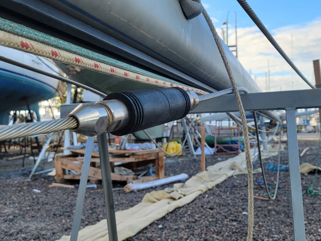
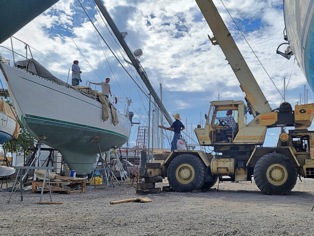
Updating the standing rigging on our Stevens 47, Totem , wasn’t an intentional part of the 40-year refit that we recently completed. We had re-rigged in 2019, anticipating our departure to the South Pacific in spring 2020. The pandemic scratched that, and we embarked on a significant refit in 2021 that instead left this rig on saw horses for a year and a half.
Putting the rig back up was among the last tasks during our extended stay at Cabrales Boatyard in Puerto Peñasco, Mexico. As we neared mast-stepping day in November 2023, my husband, Jamie, busted out his rigging kit. That’s how we refer to the 10X loupe that serves as the key for scrutinizing components at a level that human eyes just can’t do without magnification.
Some halyards showed age and wear, but we already knew this and had a replacement Dyneema/polyester double braid replacement line on hand. The one surprise? Totem ’s backstay.
Our Backstay’s Weak Link
New in 2019, the wire still looked fine, as did the swages. But two Sta-Lok insulators on the backstay —an assembly that enables that aft wire to be used as an antenna for single sideband radio—didn’t. Surface crazing on the black nylon portion of the insulators, which were added in 2008, suggested ultraviolet degradation.
During our 2019 rerig, we chose to reuse the backstay insulators. The fittings inspected well. Some people consider mechanical rigging terminals such as Sta-Lok, Hayn Hi-MOD and Norseman to be indefinitely reusable. They’re not. Jamie considers their lifespan at two rigging cycles (or about 20 years) maximum. Our old insulators met safe criteria, so we saved money by keeping them.
Still, we knew to look out for trouble. In the past few years, friends on two different cruising boats had rig failures due to broken insulators. Both crews practice good seamanship and don’t skimp on safety. Melissa White has written about losing the backstay on Galapagos (in her blog, Little Cunning Plan , and also in 48°N magazine ), three weeks into a passage from Hawaii to the Pacific Northwest. With only 500 nautical miles to Cape Flattery, Washington, their insulator snapped in half in the rolling swells of the North Pacific Ocean. They were in conditions that allowed them to stabilize the rig, and they altered course to a closer point of landfall.
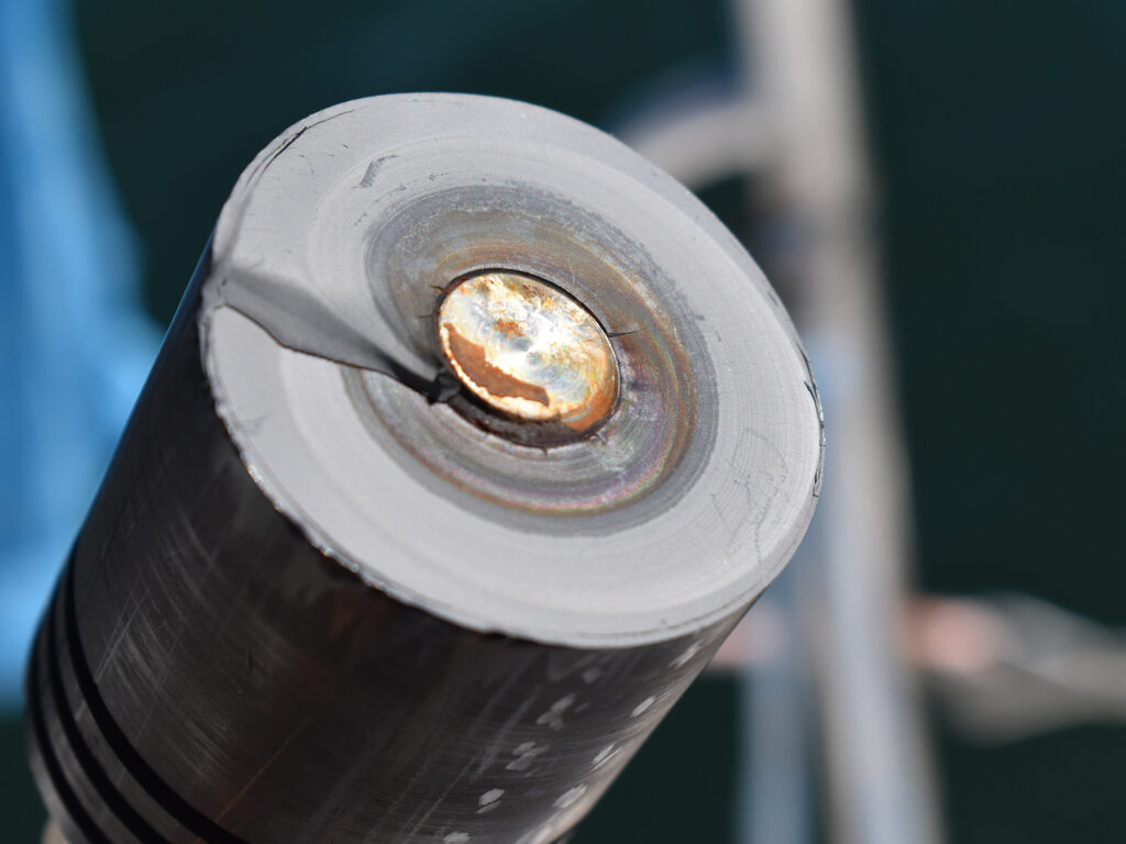
The crew of Miles wasn’t so lucky: When their insulator failed, their rig came down . Never mind the fact that they’d had a rigging inspection only months before, and no faults had been found.
When they dismasted, they were in degrading conditions approximately 100 miles east of Eleuthera, Bahamas. In an admirable effort, they secured the wreckage and bashed overnight to the nearest safe harbor in San Salvador.
So, Jamie took another look at our setup last November, and he condemned Totem ’s insulator. The conclusion was easy, but the decision about next steps was not.
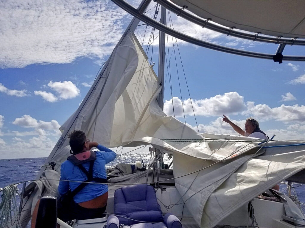
We were days from putting Totem back in the water, looking for a weather window to sail south. Five family members were flying to meet us in a bay 800 nautical miles south of the boatyard. Any delay in stepping would make us late for the family Christmas. Could we get to Puerto Vallarta with the existing backstay, or could the rig be compromised on our trip south?
And, in the time between putting insulators on the new rig in 2019 and wrapping an extensive refit in 2023, we had changed our stance on single sideband use. Once our only offshore communication, the hardware no longer earned a place on Totem because multiple satellite options are available today. Since we weren’t installing the SSB , we didn’t need new insulators. This opened options to consider in replacing the backstay.
One of those options was Dyneema, which is a strong, lightweight line made from synthetic ultra-high molecular weight polyethylene fibers. Dynex Dux is Dyneema that’s put through another cycle of heating and stretching to get every fiber in every yarn bundle to be exactly the same length. It’s lightweight, super strong and has virtually no stretch, making it a great alternative to wire for rigging.
We knew this because in 2008, Jamie had installed a Dynex Dux solent stay and inner forestay on Totem . He had also installed a Dux backstay on a friend’s boat in Puerto Rico in 2017, and loved the results.
With Totem now our focus, we reached out to Colligo Marine, the US distributor for Dynex Dux, rebranded as Colligo Dux . Colligo’s founder, co-owner and lead engineer, John Franta, helped us. Picking up the backstay became a perfect excuse for us to drive to Southern California for Thanksgiving with cousins. (Shipping into Mexico is fraught with issues.) Barely a week later, we were on our way back to Mexico with the new backstay in hand.
Shifting forward a few weeks, Totem was in Banderas Bay in time for family Christmas, after a conservative sail south with the old backstay in place. The new one was installed in the slip at Marina Riviera Nayarit. The hardest part of replacing the backstay with the mast up? Detaching and lowering the old backstay, because it was so heavy. The new stay was in place minutes later.

Wire vs. Synthetic Rigging
If Dux is so great, why didn’t we replace all of our standing rigging with it back in 2019?
Well, we did think about it. At the time, Jamie chose wire because of the cost of additional hardware necessary in the shift to synthetic rigging. We simply didn’t have the resources to consider the upgrade.
There are other considerations for a switch to synthetic rigging, too. They include abrasion, chafe, ultraviolet longevity and thermal expansion. Stainless steel wire has just as many issues and is harder to inspect well. Our new backstay was an easy choice this time around because of the weight savings, ease of installation and absence of chafe points.
We’re now getting ready to sail around 2,000 nautical miles from Hawaii to Micronesia. We aren’t sure yet if we’ll make landfall in Tarawa, Kiribati, or sail the slightly shorter distance to Majuro, Marshall Islands. Ideally, we can visit Tarawa first (it’s harder to get there later), but the weather will make the decision for us.
Meanwhile: Totem Talks will be on again before we sail west. For this next free livestream, we’ll have a circumnavigation roundtable with our friend and neighbor here in Hawaii, Dustin Reynolds . He didn’t just circumnavigate: Dustin holds a Guinness World Record for the first solo voyage around the world by a double amputee (arm and leg).Bring your voyaging questions, and sign up to be notified by email for the date of the livestream.
- More: DIY Projects , Hands-On Sailor , How To , rigging , Sailing Totem
- More How To

Top Tools for Sailboat Cruising: Must-Have Gear for 2024

Made for Shade: Cockpit Cover Options

Blackwater Wisdom for Holding Tanks

5 DIY Basics For Your Diesel Engine

North Sails Parent Company Buys Doyle, Quantum
For Sale: 1984 Camper & Nicholsons 58

Sailing Avocet : A New Adventure Begins
- Digital Edition
- Customer Service
- Privacy Policy
- Terms of Use
- Email Newsletters
- Cruising World
- Sailing World
- Salt Water Sportsman
- Sport Fishing
- Wakeboarding
Sailing Hound
Tuesday, september 6, 2016, wiring the ssb/amateur radio antenna on the backstay.
No comments:
Post a comment, little farmers cay.
Little Farmer’s Cay is a beautiful little island that is part of the Exumas. Unfortunately, we missed the regatta by a few days due to weath...
- A rocky and terrifying start to our new adventure On Sunday October 2nd we left our home port of Kittery, ME at 6:00 am to reach Gloucester by 2 pm. We obsessively checked several weather re...
- New Sailboats
- Sailboats 21-30ft
- Sailboats 31-35ft
- Sailboats 36-40ft
- Sailboats Over 40ft
- Sailboats Under 21feet
- used_sailboats
- Apps and Computer Programs
- Communications
- Fishfinders
- Handheld Electronics
- Plotters MFDS Rradar
- Wind, Speed & Depth Instruments
- Anchoring Mooring
- Running Rigging
- Sails Canvas
- Standing Rigging
- Diesel Engines
- Off Grid Energy
- Cleaning Waxing
- DIY Projects
- Repair, Tools & Materials
- Spare Parts
- Tools & Gadgets
- Cabin Comfort
- Ventilation
- Footwear Apparel
- Foul Weather Gear
- Mailport & PS Advisor
- Inside Practical Sailor Blog
- Activate My Web Access
- Reset Password
- Customer Service

- Free Newsletter

Mason 33 Used Boat Review

Beneteau 311, Catalina 310 and Hunter 326 Used Boat Comparison
Maine Cat 41 Used Boat Review

Cheoy Lee Clipper 36 & 42 Used Boat Review

Tips From A First “Sail” on the ICW

Tillerpilot Tips and Safety Cautions

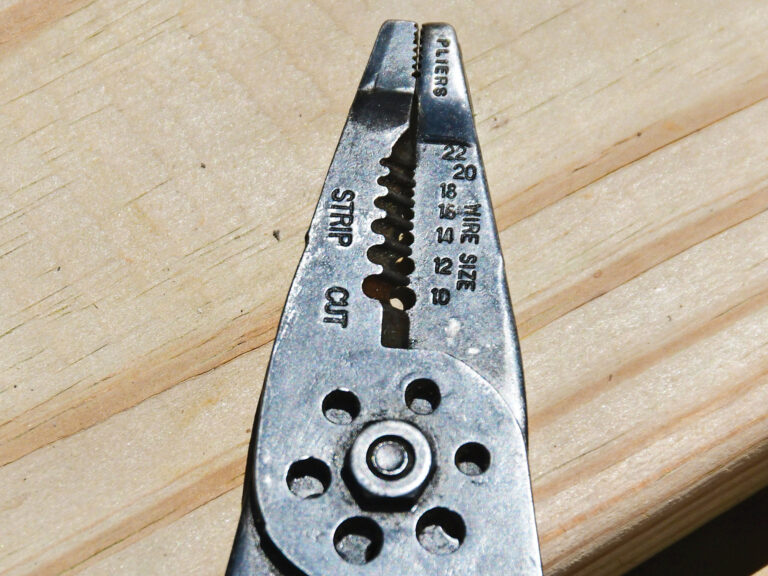
Best Crimpers and Strippers for Fixing Marine Electrical Connectors

Thinking Through a Solar Power Installation

Stopping Mainsheet Twist

Working with High-Tech Ropes
Getting a Clue for the Blown-Out Clew
Monel Seizing Wire is Worth the Extra Cost

Fuel Lift Pump: Easy DIY Diesel Fuel System Diagnostic and Repair
Ensuring Safe Shorepower

Sinking? Check Your Stuffing Box

The Rain Catcher’s Guide
Boat Maintenance for the Technically Illiterate: Part 1

Whats the Best Way to Restore Clear Plastic Windows?
Mastering Precision Drilling: How to Use Drill Guides
Giving Bugs the Big Goodbye

Galley Gadgets for the Cruising Sailor

Those Extras you Don’t Need But Love to Have

UV Clothing: Is It Worth the Hype?

Preparing Yourself for Solo Sailing

How to Select Crew for a Passage or Delivery

Preparing A Boat to Sail Solo

On Watch: This 60-Year-Old Hinckley Pilot 35 is Also a Working…

On Watch: America’s Cup

On Watch: All Eyes on Europe Sail Racing

Dear Readers
Chafe Protection for Dock Lines
- Marine Electronics
Conjuring Up Some SSB Magic
Photos by Frank Lanier
In our first article on marine single sideband, or SSB, radios, we discussed the relevancy of SSB and the benefits of having one onboard (particularly as compared with satellite communications), and we offered a market scan of the more popular radios available (see PS November 2014 ). The goal of this report is to delve into the SSB installation process, to introduce some popular accessories, and to present an initial report of our field testing; a more in-depth field test report will follow in an upcoming issue.
A typical SSB system comprises four main components: a radio (including any remote displays); an antenna tuner; the antenna itself; and the ground plane (also called the counterpoise). Worries about how to operate an SSB are often the first concern when buying an SSB, and a close second would have to be the expense and complexity of the installation itself. Do-it-yourselfers will typically find that installing the radio, remote display, and antenna tuner is no more difficult than installing any other onboard electronics, such as a VHF radio or a chartplotter. The challenge comes with the antenna and the ground plane.
Although Icom, the maker of our test radio (an Icom M802) does not make antennas or recommend specific brands, its general instructions call for a backstay antenna-which involves cutting your backstay and installing insulators-or a whip antenna (rarely used on sailboats). The Icom M802 manual also expresses a preference for a conventional ground plane such as a bronze ground plate (Dynaplate), copper mesh, and/or copper tape, the latter two often combined with existing bronze through-hulls to complete a path to the water (not necessary, but usually beneficial).
Our goal was to evaluate some of the more novel (and in some cases, controversial) products into a single system and conduct some long-term testing to see whether they provide acceptable performance-both lab testing and real-world use. In the past, weve found that these shortcut SSB installations fall under the no pain, no gain heading (we had to work to get that pun in), but given the reports weve gotten from other users, we were optimistic.
What We Tested
In our search for an easy SSB installation, we tested three products. Icom, a global company whose product line includes communications equipment and products based in the marine, avionics, land mobile, and wide-band receiver industries, provided us with its popular M802 SSB radio. GAM Electronics-a producer of high-quality, high-gain antennas for commercial fishing and consumer recreational vessels since 1958-provided its GAM/McKim split-lead SSB antenna. And Seattle-based Radio-Teck/KISS-SSB sent us its popular KISS-SSB ground plane/counterpoise.
How We Tested
Armed with a stopwatch and infinite patience, we installed each of the units according to the manufacturers instructions aboard our test boat, a 1978 Union 36 cutter. Testers evaluated them over a seven-month period while cruising along the Atlantic East Coast and northern Bahamas. This article describes our test installation, the components we chose (and why), and installation basics. Although our experience using the installed components in the field will be summarized in the conclusion, findings regarding performance are only preliminary. A full bench-test evaluation of the systems functionality will be covered in our next SSB report.
Installation comments
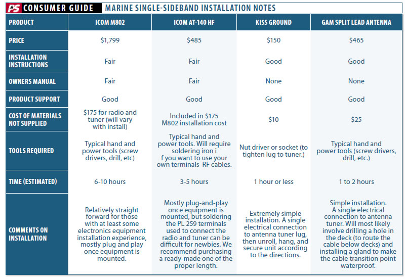
Confirming manufacturers easy-installation claims, testers were able to install the Icom M802, AT-140 tuner, KISS-SSB, and a GAM over a two-day period, although thorough planning and preparation made a big difference in efficiency. Nothing kills installation momentum like having to make multiple trips to the store for connectors, wire ties, tools, and other necessary parts that youd forgotten during the planning stage.
For do-it-yourselfers, a number of excellent books show how to install an SSB system. Three good manuals to have on hand are the Marine SSB Radio for Idi-Yachts, The Icom M802 Radio Manual for Idi-Yachts (both by Capt. Marti Brown), and Volume V Icom M802 Starting from Scratch by Commander T.L. Sparks. No license is required to install an SSB system, and the books from Brown and Sparks will be a big help when planning your installation.
Savvy dealers have also helped alleviate the grounding and antenna challenges by adding self-install kits to their product line. Some companies like Dockside DSR ( www.docksideradio.com ) have built a business around selling DIY antenna/counterpoise kits, and walking cruisers through installation process.
That being said, if you have zero electronics installation experience, this is probably not the best project to cut your teeth on. Having access to someone with SSB installation experience (whether a professional electronics technician or a knowledgeable fellow boater) will be a welcome avenue of assistance to the novice installer.
Including a conventional ground plane and antenna to the system will likely add another full day of work to the project, and depending on what your groundplane is, it may involve a haulout. This can quickly hike up the cost of an installation.
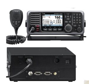
We selected the Icom M802 for our SSB system test based on features, functionality, ease of operation, and its overall popularity within the cruising community. We liked many of the features that have made the M802 so popular, particularly the fact that it can be used on both the marine HF and amateur radio HF frequencies (with the appropriate licensing). Testers also liked that the M802 included a large, easy-to-read LCD display as well as the quick, easy channel selection provided by the two large dials.
The system that we tested included the M802 transceiver, RC-25 remote control head, external speaker, and Icoms most popular antenna tuner, the AT-140. Since the transceiver for the M802 is separate from the control head, you have more options for installation. On our test vessel, we installed the control head at the navigation station while mounting the transceiver itself in an out-of-the-way, unused space beneath the chart table. This space was only 4 feet away from the batteries, reducing the length of wire runs. We mounted the AT-140 approximately 10 feet aft of the transceiver in the lazarette and as high as possible on the bulkhead. This brought it closer to the antenna, and above any possible accumulated bilge water.

Photos courtesy of John MacDougall
GAM Split-Lead SSB Antenna
Although the manufacturers description of the GAM split-lead antenna notes a number of benefits, the biggest draw for most sailors is undoubtedly ease of installation.
You can install an SSB antenna a couple of ways. On sailboats, the normal practice is to insert insulators in the backstay to create whats correctly referred to as a random-length end-fed wire antenna (as opposed to a long-wire antenna, which would be a wire antenna that is multiple wavelengths long).
Insulated backstays are fairly complex to install, and many boat owners cringe at the thought of cutting their backstay to install the needed insulators. In this type of installation, a measured length of the backstay is cut at the bottom and the top, and the cut section is re-connected with insulators. The jury is still out on the risks of having an insulator fail. Some riggers regard them as no less vulnerable than other components, so long as you follow inspection and replacement guidelines. Others avoid them. It is safe to say that it is preferable not to cut the backstay, but it is a convenient option that has generally stood the test of time.
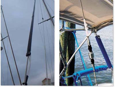
The GAM is a split-lead SSB antenna (which simply means that it has twin radiating elements) that eliminates the need for backstay removal and cutting. The center tube of the antenna housing is split, which allows users to put it on the backstay and slide it up to the desired height for the bottom of the antenna housing (15 feet or less from the connection to the tuner).
In addition to ease of installation, the manufacturer touts greater electrical conductivity and no shock hazard, etc., although the risk of shock from a backstay is minimal, and most backstays are large enough to compensate for the lack of conductivity compared to copper.
The GAM antenna housing is constructed of tough, ultraviolet-resistant, low-density polyethylene (LDPE) and is 1 5/16 by half-inch thick and fits backstays from quarter-inch and 7/16-inch in diameter. Overall, the GAM antenna is 34 feet long-so youll need a backstay that is at least that long to install it-and weighs 6 pounds.
We found the GAM split-lead antenna to be robust, well made, and extremely easy to install. From open box to mission complete, the entire process took our one-man installation team less than an hour. No muss, no fuss, and no special tools needed.
Once we slid it into place, we secured it at the base with the simple plastic clamp provided. For extra security, you can also add nylon wire ties (provided) every 4 feet during installation.
The GAM is also easy to uninstall, so its no problem to remove it for inspection, stowage, or in order to transfer it to another boat.
As to possible downsides to the GAM, it will provide a bit more windage aloft than a wire backstay, but this should be negligible. According to some experts we spoke with, the split-lead design is more temperamental, less efficient than a traditional backstay antenna, and can interfere with the operation of other onboard electronics due to coupling (i.e. closeness of GAM to the backstay).
We saw no noticeable interference problems with the GAM during our field trials, but we intend to explore this in more depth for our next article. GAM recently announced a new grounding product called the Pensum, which is their version of the KISS SSB.
If you thought the GAM was controversial, the KISS-SSB is an even hotter topic in cruising circles. This product, which eliminates the need for a traditional ground plane, generates more fist-shaking and SSB tech-nerd name calling than arguments over exactly how many jigowatts it takes to energize a flux-capacitor.
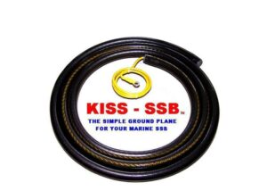
The KISS-SSB is described as a self-contained, tuned counterpoise radial ground system-a fancy way of saying that instead of actually being connected to ground, it contains radials (wires) cut to specific lengths designed to resonate throughout the marine and ham frequencies.
The perfectly measured lengths of copper and marine sealed coils act as an exact mirror image of your radiating backstay, whip, or GAM antenna, the maker explained. This is what bounces your radiated signal wave off your antenna.
These radials are housed in a 1-inch, sealed tube roughly 10 feet in length, with a 4-foot lead at one end that attaches to the ground/counterpoise lug on your tuner.
As with the GAM antenna, the big attraction for the KISS-SSB is ease of installation. Many traditional installations utilize a capacitive ground system comprising copper-foil strips (often 100 square feet or more) routed throughout the vessel and attached to every major metal onboard component along the way (fuel tanks, water, etc.). Spreading copper mesh on the inside of the boat is another approach.
A seawater ground (a direct connection to sea water using a through-the-hull ground plate, etc.) is considered by many to be the gold standard for a ground-plane, but this will involve putting an additional hole in the boat (although an unbonded bronze through-hull may also be another option). In either case, the installation headaches are there. As such, its easy to see the allure of the KISS-SSB: no holes below the waterline for installation of a bronze plate and no copper foil or copper mesh to install.
We found the KISS-SSB to be robust and extremely easy to install. Installation consists of connecting the lead to your tuner and stretching out the tube containing the radials. According to the instructions, you can run the radials pretty much anywhere-along the hull-to-deck joint, behind cabinets, underneath bunks or cushions, in the lazarette, etc. Running the tube in a straight line appears ideal, however the instructions note that a sweeping turn or even a sweeping U-turn are also acceptable.
It appears that the only installation rules that you can’t bend are that the 4-foot lead can’t be trimmed, and if the radials are coiled, the coils can’t be less than 3 feet in diameter.
Installation of the KISS-SSB aboard our test boat took about 30 minutes, including the time needed to wiggle into the lazarette to route and connect it.
Some experienced HAM operators will say that they can build their own version of the KISS-SSB for less money. While thats likely true, most sailors can’t-and even if they could, the time spent would probably exceed the purchase price, and it likely wouldnt look anywhere near as good.
Of the three products we installed for this evaluation, the Icom M802 is pretty much the best-known entity with regards to performance and reliability. It also brings the least amount of controversy to the table. In other words, while someone may prefer a different radio, theres no ruckus as to whether the M802 actually works as designed.
The same can’t be said with regard to the GAM or KISS-SSB. Despite hundreds of reportedly satisfied customers, there is no solid consensus among amateurs or professionals as to how well either of these work. The KISS-SSB bears the brunt of the criticism as many techies argue that it is technically not a tuned or resonate radial, as advertised. In their view, two random pieces of wire crimped into the bilge or lazarette would do just as well, and indeed such an arrangement would also work to some degree. Well explore this further in Part 3.
In our view, the answer to the question, Do these products work? is not easily answered with a simple yes or no. They worked well during our test cruise, but we werent trying to reach Madagascar, nor have we completed bench testing their performance. A more reasonable question to ask is whether they meet your needs. Theres no doubt that an ardent SSB or HAM enthusiast can install a better system and tweak it to connect with similar enthusiasts half-way around the world. But, if a less tech-savvy user can more-easily enter the world of SSB by installing a system with minimal fuss that meets all their needs to check email or speak with other cruisers in their corner of the world, is it a bad system?
During our preliminary tests, weve used the system for both voice communications and email (see product update on top right ). It has worked perfectly so far during our initial email checks, which are pretty easy to assess.
The voice checks have been harder to evaluate due to a number of variables, including weather, time of day (which determines which frequencies to use), location, and the quality of equipment on the vessels we conversed with. We hope that more testing with these products will provide a more definitive answer in Part 3.
- Installing the Icom M802
- Making a Mayday Call on Marine SSB Radio
- PS Tests Farallon’s Pactor-4 Modem, SailMail
- Professional Versus DIY SSB System Installs
RELATED ARTICLES MORE FROM AUTHOR
Leave a reply cancel reply.
Log in to leave a comment
Latest Videos

The Perfect Family Sailboat! Hunter 27-2 – Boat Review

Pettit EZ-Poxy – How to Paint a Boat

The Boat From True Spirit – Sparkman & Stephens

Top 5 Boat Hacks – Boat Maintenance Tips and Tricks
Latest sailboat review.

- Privacy Policy
- Do Not Sell My Personal Information
- Online Account Activation
- Privacy Manager
- Subscription Management Portal
- Airtime Customers:
- Activate New Services
- Resume/Modify
- Stop Service

GAM/McKim HF-SSB Split Lead Antenna for Sailboats
$ 465.00
The GAM/McKim split lead single side band antenna is a favorite amongst sail boaters because it eliminates the need for backstay insulators forever. The split lead antenna simply press fits onto your existing backstay wire with no special tools or equipment required. The GAM/McKim is secured at the base by a hard grade plastic T clamp and requires a back stay length of at least 34 feet.
Communications Expert Gordon West Reports, “I have done numerous SSB ham and marine radio checks with this system and have found no discernible signal losses, even when used with a well-grounded backstay aboard a steel-hulled vessel.” The Split Lead antenna’s. . .”twin radiating elements. . .bang out a signal as if they were suspended in mid-air.” – from Sail Magazine’s “Ask Sail” column, October 2005.
The GAM/McKim Split Lead Antenna is priced to compete with conventional backstay insulators (including swaging costs) and less expensive than many insulators utilizing reusable terminals.
Made in the USA
In Stock | Ready to Ship
KISS-SSB Ground Plane for HF Radio
A proper ground plane is key to getting the most out of your SSB Radio. The KISS marine SSB ground plane will maximize the performance of your SSB without underwater holes in the hull or unnecessary wiring.
The KISS-SSB is a US Patented marine SSB ground plane system. This Icom-endorsed principle is the one and only complete antenna counterpoise system. It does not require any holes under the water-line in the hull for a bronze plate, copper foil, or copper mesh. The system has many feet of exact length wire radials built in.
Unlike other ground plane systems, the KISS is simple to install. Simply attach one end to your SSB radio, and uncoil the remaining wire anywhere convenient, such as in the bilge. That's all there is to it - your KISS is ready to go.
Eliminates possible ground loops also!
After a normal installation time of less than thirty minutes, the KISS-SSB is completely maintenance free. Unlike the bronze plate that requires constant cleaning, and the copper foil that is subject to constant corroding, the KISS-SSB lets you simply enjoy paradise!
Meticulously Handmade in Beautiful North Idaho, USA
Description
Additional information.
Click here to download a PDF of product features.
Safety
The split lead antenna installation requires no alteration of the backstay thus preserving full mechanical integrity of the backstay wire. All RF elements of the antenna are fully insulated eliminating the possibility of the shock hazard posed by the bare wire connection in conventional backstay antennas.
Ease of Installation
No cutting, no swaging, no measuring, no special tools, no special skills required. Simply press fit the GAM/McKim over the existing backstay wire, clamp at bottom and secure in place with included Zip-Ties. Click here for installation instructions.
Performance
Active elements are designed for RF, meaning they are more conductive than the stainless steel backstay wire. Lead wire connections are waterproof and electrically sound. The antenna’s insulated housing reduces precipitation static, often associated with heavy squalls and thunderstorms.
Stowage and Portability
The Split Lead antenna can be coiled up to a diameter of approximately 26” for ease of storage. It can be easily removed when the mast or backstay require work and can readily be transferred from one vessel to another.
The outer housing is very durable, resistant to weathering and, since it is under no mechanical stress, should last for many years in the marine environment.
| Weight | 8 lbs |
|---|---|
| Dimensions | 24 × 24 × 2 in |
| Brand | GAM |
You may also like…

Related products

Communications Made Simple for Cruisers: 2nd Edition
Icom m802/m803 NMEA0183 GPS Adapter
Icom Radio MMSI Reprogramming
Product categories.
- Authorized Icom Marine VHF and SSB Dealer 44 44 products
- Authorized PACTOR Modem Dealer 7 7 products
- Professional Services 4 4 products
- Special Deals 1 1 product
- SeaTech Packages 4 4 products
- PC Weather 4 4 products
- Mac Weather 2 2 products
- Tablet Weather 2 2 products
- Chartplotter Weather 1 1 product
- Books 9 9 products
- AIS Transponders 5 5 products
- Email Products and Services 5 5 products
- Global Cellular 1 1 product
- Activation 12 12 products
- Reusable Iridium SIMs 3 3 products
- Iridium Go! 5 5 products
- Iridium Phones 6 6 products
- Push-to-Talk 1 1 product
- Viasat Maritime 1 1 product
- Starlink Accessories 8 8 products
- PACTOR 3 3 products
- SSB Accessories 15 15 products
- Fixed VHF 21 21 products
- Handheld VHF 10 10 products
Recent Articles
- Raymarine Axiom Wireless Features Overview
- FCC Approves change to amateur radio rules – Allowing PACTOR4 use!
- Establishing a VPN Connection to your Starlink connected boat
- Leading Peplink USA Distributor features Narwhal Wi-Fi Onboard Systems in new Case Study
- Why you need a backup communications solution…

- Forum Listing
- Marketplace
- Advanced Search
- Welcome To SailNet
- New Member Introductions
- SailNet is a forum community dedicated to Sailing enthusiasts. Come join the discussion about sailing, modifications, classifieds, troubleshooting, repairs, reviews, maintenance, and more!
SSB back stay antenna attachment
- Add to quote
I reattached my SSB antenna to my back stay today. In the past I have twisted the center conductor together with the shield, soldered this, then attached to the back stay with bulldog clamp. Not the best results. Today I only attached the center conductor to the stay and cut shielding back so no contact is made with backstay. Should the shield be in contact with backstay or not? Never seen this mentioned anywhere. much obliged, Randy S/V Nautilus, currently San Carlos, Mexico
Most people do not use coax for their antenna lead, so this question usually isn't applicable. All that is needed is a wire from the coupler to the backstay, and that wire becomes part of the antenna itself. If you use coax, then either connect the shield to the center conductor at both ends, or strip it back at both ends (essentially a single wire). I'd opt for the latter, but I wouldn't use coax at all. Propagation isn't good right now, so a single test might not tell how the antenna is operating in general. Mark
Thanks so much Mark. This is as I expected but often one must wade through the "Zen" of making it too complicated and return to basics. Randy
Ancor GTO 15 High Voltage Cable (Sold by the Spool) - 150102
Just in case this isn't known, the length of the wire from the coupler to the backstay antenna, plus the length of the antenna is an important measurment for an SSB. I offer it, in the event someone just threw a random amount of coax at it.
For a long wire antenna using a backstay, the length doesn't really matter much. One would ideally like to avoid 1/2 wavelengths of the bands they are interested in, but this isn't very adjustable with a backstay already cut and a coupler wire that should be as short and straight as possible. It would be better to be at a 1/2 wavelength than have a 10' coil of extra wire between the coupler and antenna, for example. Mark
- ?
- 176K members
Top Contributors this Month

Image Unavailable

- To view this video download Flash Player
Single Side Band Sailboat Backstay Antenna
| Antenna | Radio |
| Brand | Gam/McKim |
| UPC | 852671072226 |
| Manufacturer | GAM Electronics |
Looking for specific info?
Product description.
The GAM/McKim split lead single side band antenna is a favorite amongst sail boaters because it eliminates the need for backstay insulators forever. The split lead antenna simply press fits onto your existing backstay wire with no special tools or equipment required. The GAM/McKim is secured at the base by a hard grade plastic T clamp and requires a back stay length of at least 34 feet.
Product information
| Package Dimensions | 24.1 x 23.9 x 2 inches |
|---|---|
| Item Weight | 7.2 pounds |
| ASIN | B00HEPIE6Q |
| Is Discontinued By Manufacturer | No |
| Wireless communication technologies | HF |
| Other display features | Wireless |
| Manufacturer | GAM Electronics |
| Date First Available | December 18, 2013 |
Customer reviews
- 5 star 4 star 3 star 2 star 1 star 5 star 0% 0% 0% 0% 0% 0%
- 5 star 4 star 3 star 2 star 1 star 4 star 0% 0% 0% 0% 0% 0%
- 5 star 4 star 3 star 2 star 1 star 3 star 0% 0% 0% 0% 0% 0%
- 5 star 4 star 3 star 2 star 1 star 2 star 0% 0% 0% 0% 0% 0%
- 5 star 4 star 3 star 2 star 1 star 1 star 0% 0% 0% 0% 0% 0%
Customer Reviews, including Product Star Ratings help customers to learn more about the product and decide whether it is the right product for them.
To calculate the overall star rating and percentage breakdown by star, we don’t use a simple average. Instead, our system considers things like how recent a review is and if the reviewer bought the item on Amazon. It also analyzed reviews to verify trustworthiness.
No customer reviews
- Amazon Newsletter
- About Amazon
- Accessibility
- Sustainability
- Press Center
- Investor Relations
- Amazon Devices
- Amazon Science
- Sell on Amazon
- Sell apps on Amazon
- Supply to Amazon
- Protect & Build Your Brand
- Become an Affiliate
- Become a Delivery Driver
- Start a Package Delivery Business
- Advertise Your Products
- Self-Publish with Us
- Become an Amazon Hub Partner
- › See More Ways to Make Money
- Amazon Visa
- Amazon Store Card
- Amazon Secured Card
- Amazon Business Card
- Shop with Points
- Credit Card Marketplace
- Reload Your Balance
- Amazon Currency Converter
- Your Account
- Your Orders
- Shipping Rates & Policies
- Amazon Prime
- Returns & Replacements
- Manage Your Content and Devices
- Recalls and Product Safety Alerts
- Registry & Gift List
- Conditions of Use
- Privacy Notice
- Consumer Health Data Privacy Disclosure
- Your Ads Privacy Choices
Visit our Popular Forums
- Monohull Sailboats
- Multihull Sailboats
- Powered Boats
- General Sailing
- Antares Yachts
- Fountaine Pajot
- Lagoon Catamarans
Cruising Business
- Boat Classifieds
- General Classifieds
- Crew Positions
- Commercial Posts
- Vendor Spotlight
Life Aboard a Boat
- Provisioning: Food & Drink
- Families, Kids, & Pets Afloat
- Recreation, Entertainment, & Fun
- Boat Ownership & Making a Living
- Liveaboard's Forum
Seamanship, Navigation & Boat Handling
- Seamanship & Boat Handling
- Training, Licensing, & Certification
- Health, Safety, & Related Gear
- Rules of the Road, Regulations, & Red Tape
Engineering & Systems
- Const. / Maint. / Refit
- Product / Service Reviews
- Electronics: Comms / AV
- Electrical: Batts / Gen / Solar
- Lithium Power Systems
- Engines & Propulsion
- Propellers & Drive Systems
- Plumbing / Fixtures
- Deck Hdw: Rigging / Sails
- Aux. Equipment & Dinghy
- Anchoring & Mooring
Photo Categories
- Member Galleries
- Life Onboard
- Sailing in the Wind
- Power Boats
- Cruising Destinations
- Maint. & Boat Building
- Marine Life
- Scuba Diving & Divers
- General Photos
Recent Photos

Listing Categories
- African Cats
- view more »
- Crew Wanted
- Crew Available
- Enhance Your Account
- Meet the Mods
- Meet the Advisors
- Signup for The Daily Cruiser Email

IMAGES
COMMENTS
PS, 7/18: Rumor has it that Sail SSB expert Gordon West tested this antenna and found that it worked as well as an insulated backstay, even when fitted over the grounded stay of a steel boat. I've also seen reports that it many cases (depends on wire fittings) it is actually less expensive than the traditional insulator set up.
svHyLyte. 3491 posts · Joined 2008. #6 · May 16, 2012. Bill Trayfors, an experienced cruiser and knowledgeable radio technician active on several sailing forums taught me that an effective connection can be made by attaching a ring-connector to the end of the cable between your antenna tuner and the back-stay with an appropriate heat shrink ...
Sailboat - 48N x 89W. Feb 3, 2005. #5. SSB Antennas. The traditional guidelines for a Backstay Antenna are to have the bottom insulator 7' off the deck, and 3' down from the masthead. Insulated sections of backstays longer than 35' are not necessary, however a longer antenna may perform better. The RF output from the tuner can be as high as ...
This is a unit that press fits on the backstay wire. The cost of the new separate signal halyard wire antenna was less than $20. The total cost of the new backstay was about $400, including the signal halyard antenna. I separated the SSB antenna from the grounded backstay by leading the antenna wire through an extension on our radar post.
Our Backstay's Weak Link. New in 2019, the wire still looked fine, as did the swages. But two Sta-Lok insulators on the backstay—an assembly that enables that aft wire to be used as an antenna for single sideband radio—didn't. Surface crazing on the black nylon portion of the insulators, which were added in 2008, suggested ultraviolet degradation.
The proper cables are very important for any type of radio installation. The wire from the antenna tuner to the backstay is GTO-15 High Voltage Cable. The cable itself is part of the antenna so the tuner needs to be as close to the backstay as possible. Since our boat is on the smaller side, finding a mounting space was very difficult.
While vertical whip antennas and backstay antennas are both more-or-less vertical, I wouldn't call them equal in most cases. They're both -- effectively -- random-length end-fed radiators. ... W4GE, served as Waterway Net Control from his 25' boat, using a random wire antenna and radials inside his hull. He had a strong signal from Charleston, ...
The GAM/McKim split lead single side band antenna is a favorite amongst sail boaters because it eliminates the need for backstay insulators forever. The split lead antenna simply press fits onto your existing backstay wire with no special tools or equipment required. The GAM/McKim is secured at the base by a hard grade plastic T clamp and ...
Shortman said: There is an interesting note on SSB antennas in the current issue of Sail by Gordon West. BoatWorks Ask Sail p.87. References GAM/McKim antennas that don't need an insulated backstay, the use of a whip antenna, or running a GTO-15 cable inside a double braid sheath & hoisting up the mast when you need.
The GAM antenna housing is constructed of tough, ultraviolet-resistant, low-density polyethylene (LDPE) and is 1 5/16 by half-inch thick and fits backstays from quarter-inch and 7/16-inch in diameter. Overall, the GAM antenna is 34 feet long-so youll need a backstay that is at least that long to install it-and weighs 6 pounds.
Re: HF antenna cable to the backstay. If the backstay "is" the antenna, then you would use GTO-15 wire from the tuner to the backstay. The GTO-15 wire is insulated and looks like coax, but it is not. It is a single wire within the insulation. The connection would be made where the GTO-15 and the backstay meet.
Location: Sherbrooke, QC. Boat: Paceship P29 & Morgan OI 416. Posts: 34. Alternate backstay antenna. I'm planning an SSB installation on my 41" ketch next Spring and while mining the forum for ideas and advice, I was quite intrigued by this post advocating the use of a sloper antenna (top fed) for HF. Isolate the backstay right at the masthead ...
Locate the automatic tuner as close under deck as you can. Then, take a length of GTO-15 insulated wire and connect the tuner to your "alternate backstay". You do, of course, need an RF counterpoise or ground system, just as you do with any end-fed antenna system. Here's a pic showing the lower-end detail.
GAM/McKim HF-SSB Split Lead Antenna for Sailboats. $ 465.00. The GAM/McKim split lead single side band antenna is a favorite amongst sail boaters because it eliminates the need for backstay insulators forever. The split lead antenna simply press fits onto your existing backstay wire with no special tools or equipment required.
Standard advice for installing a HF Radio on board your boat involves two big steps: Cut the backstay near the stern and near the top of the mast and install insulators to make that isolated section your vertical antenna. Drill a hole in your hull and install a "ground shoe" (A dynaplate) to serve as the transmitter's ground.
The GAM/McKim split lead single side band antenna eliminates the need for backstay insulators forever. The split lead antenna simply press fits onto your existing backstay wire with no special tools or equipment required. The GAM/McKim is secured at the base by a hard grade plastic T clamp and requires a back stay length of at least 34 feet.
Ancor GTO 15 High Voltage Cable (Sold by the Spool) - 150102. Ideal as a coupler output to antennas, Ancor's GTO 15 High Voltage Cable provides marine grade, 14 gauge tinned copper lead-in wire for HAM and SSB antennas. Features: High voltage, premium tinned copper wire Great coupler output to antenna I. www.defender.com.
The split lead antenna simply press fits onto your existing backstay wire with no special tools or equipment required. The GAM/McKim is secured at the base by a hard grade plastic T clamp and requires a back stay length of at least 34 feet. Brief content visible, double tap to read full content.
No way. Trap dipoles, at best, perform about the same as non-trap resonant dipoles. Furthermore, inverted V antennas have a high angle of radiation which do not favor DX (long distance) propagation. I'll agree with you that the traditional backstay antenna isn't a great performer, being nothing more than an end-fed random-length sloper.
Joint-stock company Tomskneft, a Tomsk-based oil production company controlled by Rosneft, is located in Strezhevoy, and the town grew up around the company's expanding needs. [8] Most of the town's housing and all of its major public amenities were constructed around the company's needs in the 1960s and 1970s.
Kargasok. Kargasok ( Russian: Каргасок) is a rural locality (a selo) and the administrative center of Kargasoksky District of Tomsk Oblast, Russia, located on the left bank of the Ob River, 460 kilometers (290 mi) from Tomsk, the administrative center of the oblast. Population: 8,127 ( 2010 Russian census); [1] 8,547 ( 2002 Census); [2 ...
Travel forums for Tomsk. Discuss Tomsk travel with Tripadvisor travelers
Interestingly enough, my first boat was a ketch, my antenna was run from the transom to the top of the mizzen. Thinking to increase the wire/antenna lenght, I concocted a system to extend the wire/antenna to the main mast, much like a triatic stay, but thru' experimentation with other hams found that the inclined angle between main and mizzen ...
Comment - This license tag is also applicable to official documents, state symbols and signs of the Russian Soviet Federative Socialist Republic and the Union of Soviet Socialist Republics (union level).. Warning - This license tag is not applicable to drafts of official documents, proposed official symbols and signs, which can be copyrighted.. Warning